What is the 2:1 Ratio For Linear Plain Bearings?
The 2:1 Ratio represents the maximum allowable moment arm distance relative to bearing length without causing binding or motion restriction, ensuring optimal performance in plain linear bearings. PBC Linear introduced this groundbreaking concept for self-lubricating linear bearings many years ago, which is now widely recognized as the industry standard by plain bearing manufacturers. This Binding Ratio defines the geometric relationship between the moment arm distance and bearing length.
Definition of the Binding Ratio for Plain Linear Bearings
 The 2:1 Ratio or Binding Ratio is officially defined as the maximum ratio of moment arm distance to bearing length which will not bind (prevent motion). The Binding Ratio is often displayed numerically as “X: Y,” where “X” is the moment arm distance and “Y” is bearing length. It is best practice to spread the bearings on the shaft as far apart as the application will allow.
This principle is not influenced by load, edge loading, or the type of driving force used. Plain linear bearings will bind regardless of whether they are hand-driven or mechanically driven. The root cause of binding lies in friction, and the only way to ensure smooth, reliable operation is by adhering to the 2:1 Ratio. This rule holds true for any PBC Linear products that use plain linear bearings including the Gliding Surface Technology linear slides.
Example of the 2:1 Ratio for Plain Linear Bearings
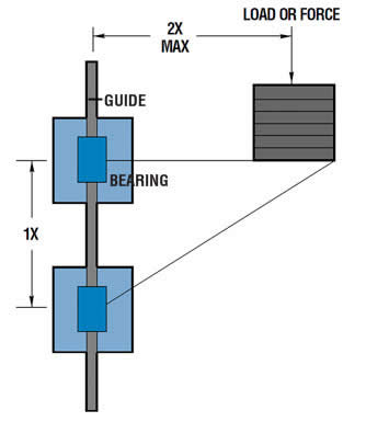
In the image, "2X" represents the distance from the shaft to the load or applied force, while "1X" is the distance between the bearings along the shaft. To maintain the critical 2:1 Ratio, if 2X equals 10 inches, then 1X must be at least 5 inches. Failing to adhere to this ratio can result in binding or restricted movement in the application.
Troubleshooting Binding in Plain Bearing Applications
There are five simple strategies that can resolve binding or stick-slip problems in most applications. These are listed in no particular order, and the best solution depends on what is most beneficial and feasible for your specific application:
- Reduce Moment Arm Distance: This will shift the application out of the binding or stick-slip zone and into the smooth motion zone.
- Increase Bearing Length: Options include switching to a longer bearing/carriage, increasing the spacing between multiple bearings, or adding a second bearing to a single bearing system.
- Add a Counterbalance: A counterbalance reduces the moment, which in turn lowers the resulting forces and the frictional forces.
- Remove External Forces: Misalignment or damage to a shaft/rail is a common source of external forces. Correcting these issues can resolve binding.
- Reduce Bearing Friction: Adding lubrication or switching to a different type of lubrication can lower the overall coefficient of friction.
If these strategies don't solve the binding or stick-slip issue, contact a PBC Linear application engineer for additional troubleshooting assistance.
Troubleshooting Binding in One Direction of Motion
In some applications, smooth motion may occur in one direction but binding in the opposite direction. This is typically caused by previously unaccounted-for forces. While forces are often accounted for along one axis, they are rarely confined to just one. If a force is applied at a distance greater than the Binding Ratio in one axis, the entire system may experience stick-slip motion or even complete binding. This can make troubleshooting frustrating, as the system seems to function correctly only half of the time. The most common solution is to increase the bearing length, either by increasing the distance between bearings or switching to an extended-length bearing.
Comments (0)
This post does not have any comments. Be the first to leave a comment below.
Featured Product