The process splits materials at the molecular level under a non-contact process with tremendous speed resulting in no material loss, chips, lateral cracks, protrusions, hooks, and flares, or any other forms of contaminants.
 What is Zero-Width Laser Cutting Technology?

Article from | Laser Photonics
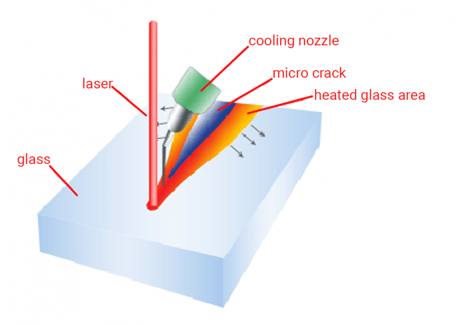
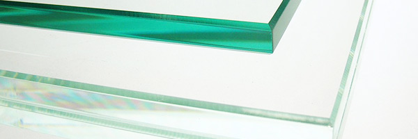
Zero Width Laser Cutting Technology™ is a method and process for cutting glass and other brittle non-metallic materials. The process splits materials at the molecular level under a non-contact process with tremendous speed resulting in no material loss, chips, lateral cracks, protrusions, hooks, and flares, or any other forms of contaminants. Laser Photonics Corporation developed and owns the patent.

The technique uses a laser-controlled Power Density profile on the material surface to generate the subsurface forces greater than intermolecular connections. This technology has dramatically improved the substrate separation process, specifically for the latest generations (Gen 6, 7, and 8) glass panels for Flat Panel Display (FPD) manufacturing. Zero Width Laser Cutting Technology has been optimized for thin-glass applications up to 1.0mm, but can be applied to other thicknesses.
The method uses a non-contact laser-induced internal stress to produce a controlled separation. Since the technique is non-contact, the surface degradation associated with mechanical scribe and break is eliminated. Yield loss as a result of particulate damage is also greatly reduced. Cutting substrates in cleanroom conditions becomes feasible with Zero Width Laser Cutting Technology leading to the ability to introduce a production line concept into cleanroom substrate manufacturing. This has not been possible before because of debris generated during cutting and edge grinding which will not be generated during Zero Width Laser Cutting Technology processing. In addition, cleaning facilities can also be substantially reduced. These factors offer a cost-effective solution to manufacturing space and efficiency. Systems that utilize Zero Width Laser Cutting Technology can achieve much deeper penetration of a precisely controlled micro-crack. The process creates high-speed scribe lines (up to 1 meter per second, depending on the material type and thickness) in a prearranged manner, with no molecules leaving the surface, dramatically improving the substrate separation process.

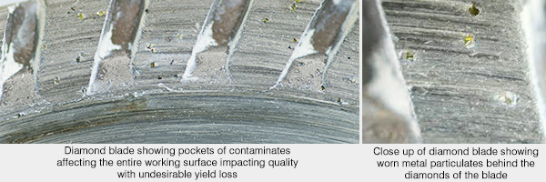
The Zero Width Laser Cutting Technology method incorporates cooling of the glass surface following controlled heating, with the correct power density profile, this creates the intermolecular separation of the glass substrate to a certain depth. Depth ( t ) has an inverse relation to the speed ( v ) of cutting, assuming that power ( P ) is constant. This means that the slower the speed the deeper the separation that is formed. Both mathematical models and empirical data support these conclusions and field experience has verified these findings. Zero Width Laser Cutting Technology is the only technology available in the world with a non-dimensional cutting line. Unlike traditional methods, such as those involving diamond blades, waste material created by the cutting process can be completely eliminated.

Yesterday’s solution: imprecise, wasteful cutting with a diamond blade
The content & opinions in this article are the author’s and do not necessarily represent the views of ManufacturingTomorrow
Comments (0)
This post does not have any comments. Be the first to leave a comment below.
Featured Product

