Computational Fluid Dynamics (CFD) has emerged as a vital tool for analyzing and solving thermal management challenges, enabling teams to explore solutions and mitigate risks before investing in physical resources. This article will provide a general overview of CFD.
Understanding Computational Fluid Dynamics in Electrical Engineering
Jeff Smoot, VP of Apps Engineering and Motion Control at Same Sky | on behalf of DigiKey
In the realm of electrical engineering, managing heat transfer and cooling systems is crucial for ensuring reliability and efficiency. Guesswork and hope are impractical, while trial-and-error methods are costly and inefficient. By conceptualizing heat as a fluid, engineers can employ a precise and realistic modeling approach. Computational Fluid Dynamics (CFD) has emerged as a vital tool for analyzing and solving thermal management challenges, enabling teams to explore solutions and mitigate risks before investing in physical resources. This article will provide a general overview of CFD, including how it works and its benefits in electronics design.
CFD – the basics
CFD uses numerical algorithms to solve complex, non-linear partial differential equations that govern fluid mechanics and heat transfer. These computations create detailed three-dimensional models, accurately representing the spatial and temporal dynamics of physical systems. This method provides engineers with realistic insights without incurring the high costs of experimental setups.
CFD transforms thermal analysis by simulating the interactions between fluids and solids and assessing convective behavior within surrounding fluids. The technique integrates the three primary methods of heat transfer—conduction, convection, and radiation—into fluid flow simulations. This results in comprehensive thermal behavior assessments, which are indispensable in electrical engineering applications.
Most CFD software is designed for general-purpose applications, modeling phenomena such as heat transfer, airflow, phase changes, and more. However, specialized CFD tools are available that focus specifically on heat transfer, particularly within electronic devices, where accurate modeling of thermal behavior is critical for ensuring performance and reliability. Unlike general-purpose CFD tools, these niche solutions streamline processes by tailoring features to specific applications. For instance, dedicated software can model integrated circuit packages, circuit boards, heatsinks, heat pipes, and fans. A key capability includes determining the operating point of a cooling fan based on calculated system resistance, ensuring sufficient airflow without unnecessary power consumption. Additional CFD thermal analysis data can include:
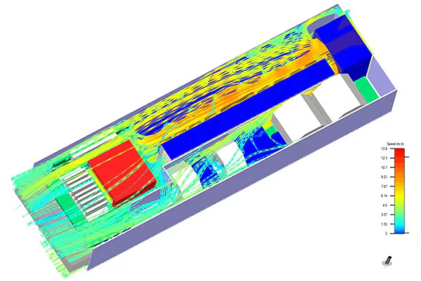
- Airflow fields and patterns: Understanding airflow behavior around electronic components
- Heat flux rates: Quantifying heat transfer intensity across surfaces
- Hotspot identification: Detecting localized regions of excessive heat
- Temperature distribution: Mapping thermal gradients across systems
- Heat transfer rates: Evaluating the efficiency of cooling mechanisms
This data empowers engineers to optimize designs for effective heat dissipation, enhance cooling strategies, and prevent thermal failures. These insights are integral to maintaining system reliability and extending the lifespan of electrical devices.

Figure 1: Example of CFD analysis. (Image source: Same Sky)
CFD – how it works?
Computational fluid dynamics rely on three core principles derived from physics: the conservation of mass, conservation of momentum, and conservation of energy. These principles are mathematically expressed through the Navier-Stokes equations. When a CFD model is correctly configured based on these equations and converges to a solution, it inherently satisfies the fundamental laws of physics, ensuring the reliability of the results.
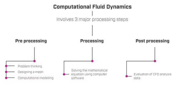
A standard CFD analysis typically involves three primary processes. However, additional steps—both preliminary and post-processing activities—can significantly enhance the comprehensiveness and accuracy of the analysis.

Figure 2: CFD involves three major processing steps. (Image source: Same Sky)
Before initiating a CFD analysis, the problem must first be formulated as a partial differential equation system. This foundational phase is critical as it defines the governing equations—typically based on the Navier-Stokes equations—that describe the physical phenomena under study. This step ensures that the mathematical model accurately represents the problem's physical behavior, serving as the starting point for CFD analysis.
- Pre-processing stage: In the pre-processing stage, the CFD software converts the partial differential equations into discrete algebraic equations. A key activity during this phase is mesh generation, where the computational domain is divided into structured or unstructured elements (e.g., triangles, quadrilaterals, or tetrahedrons).
Refining the size of mesh elements in critical regions of the flow field, particularly near boundaries or high-gradient areas, ensures a more accurate representation of the physical phenomena. This step directly influences the quality and precision of the simulation results.
- Processing stage: During the solving stage, CFD simulation software numerically solves the algebraic equations generated in the pre-processing phase. The simulation process is heavily influenced by several factors that determine computation time and accuracy, including:< >Computer hardware capabilities, such as processor speed and memoryVectorization and parallelization techniques, which optimize computation speedData structures, ensuring efficient data handlingStopping criteria, which define convergence and simulation completionMesh size and quality, as well as temporal resolution for transient simulationsProgramming language, affecting code efficiency and executionPost-processing stage: The post-processing stage focuses on analyzing and interpreting the simulation results. Data from the CFD simulation is extracted and visualized through images, graphs, and tables, providing insights into various parameters. Based on these findings, engineers may determine whether further tests, optimization, or redesigns are necessary. Effective post-processing is critical for communicating results and identifying actionable steps, whether for validating the design, improving system performance, or troubleshooting issues.
Solving thermal hotspots
CFD simulations provide a high level of precision and valuable insights compared to physical experiments, particularly for complex flow systems where detecting thermal hotspots is challenging. Thermal hotspots are localized regions with temperatures significantly higher than their surroundings. If not addressed, these hotspots can lead to heat accumulation over time, resulting in severe outcomes such as system malfunctions, failures, or irreversible damage to the product. These issues can compromise the longevity of electronic devices and potentially jeopardize user safety.
By employing CFD thermal simulations, engineers can accurately predict and visualize thermal distribution within a product's design. This capability allows for the early identification of potential thermal hotspots. With this information, targeted design modifications—such as enhancing heat dissipation mechanisms, optimizing material properties, or reconfiguring airflow paths—can be implemented to prevent excessive heat buildup. As a result, the system becomes more resilient to thermal stresses, reducing the likelihood of damage and extending its operational lifespan.
Cost and time savings with CFD
Engineers continually aim to develop better-performing electronic products, but the decision to proceed with mass production often depends on the results of rigorous real-world testing. The design process for modern electronics is increasingly intricate, with products becoming more compact and requiring significant investments of time and resources to develop even a single prototype. After a prototype is produced, it undergoes thermal strain tests to evaluate its durability, physical properties, and real-world performance. Only prototypes that pass these tests move forward to mass production, whereas failure results in a complete loss of the initial investment.
CFD offers a powerful alternative by enabling the simulation of real-world conditions on virtual models of electronic products. Through CFD, engineers can conduct heat transfer analyses on their designs, identifying thermal issues and refining the model without the need for physical prototypes. This iterative simulation process provides precise results, including detailed visualizations of flow patterns and thermal distribution, offering a deeper understanding of complex flow and heat transfer systems than traditional physical testing.
Conclusion
By leveraging CFD simulations, engineers can efficiently optimize product designs, reducing the time and cost associated with physical prototyping. This approach minimizes the risk of failure, accelerates the development process, and ensures that the final product is ready for mass manufacturing with improved performance and reliability. If any questions should arise on where and how to get started with CFD, Same Sky’s thermal design services and range of thermal management components are here to help.
Disclaimer: The opinions, beliefs, and viewpoints expressed by the various authors and/or forum participants on this website do not necessarily reflect the opinions, beliefs, and viewpoints of DigiKey or official policies of DigiKey.
The content & opinions in this article are the author’s and do not necessarily represent the views of ManufacturingTomorrow
Comments (0)
This post does not have any comments. Be the first to leave a comment below.
Featured Product

