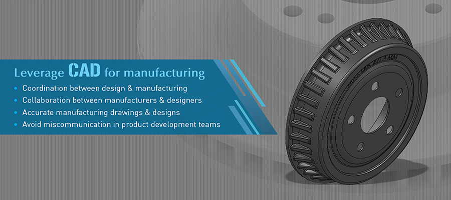
Maybe, it is not all about innovation; it is about the integration of designs in the right sequential manner that does not hinder the efficiency of new designs.
Remedies for Manufacturing of Innovative Industrial Product Design
Usha B. Trivedi | Hitech iSolutions LLP
The manufacturing industry is thriving for innovative industrial components with special attention given to aesthetics and ergonomics. Even a small product manufactured from the cheapest sheet metal also has to meet innovative process in lieu of traditional manufacturing processes that consumes time and evolves the same results.

Manufacturing companies are striving to deliver unique products with innovative process and meeting customer demands. Side by side, global manufacturing markets are becoming increasingly competitive, design cycles are shrinking, and the customer is becoming selective. Considering these tall orders, manufacturing industry steers towards success leveraging innovation with CAD product designing. However, so many times, even the most innovative products fail in markets and results are scathing for businesses.
Market Agility and Industrial Designs Innovations
When the most innovative products fail, the design engineers need to rethink the actual market needs and focus on integrating designs with manufacturing processes. A great deal of design success lies in manufacturing methods and processes.
The heat treatment applied to steel before fabrication can make or break the metal – that is makes it more elastic or turn into brittle. Thus, delivering right manufacturing drawings and designing right kind of products will govern the success of the product in markets, more than innovation and ergonomics.
Challenges that pull down the innovative design performance
Even today, there are manufacturers who treat design as a separate process. Each team in the company, designing, procurement, manufacturing etc. work in a siloed environment and independent sub-teams divided by individual work.
Such an environment tends to add challenges in the process of seamless product development and its performance in the market. Due to disjoint within the product development teams, even the critical information is delivered in fragments and design intelligence is lost in the process leading to wreak havoc.
Obstruction to seamless translation of design to manufactured product
Any design problems identified during manufacturing will further cause delays. The most common example is drilling a hole on the surface of the metal sheet or stack up a tolerance that will cause misalignment when holes are mounted.
But the manufacturers and shop floor foremen will immediately identify such inconsistencies in the drawings at the first look because they have kept the machines abreast since years. When manufacturers and designs work in collaboration and exchange design information early, the translation process from design to manufactured product becomes seamless.
Constructing a bridge between drawings and manufacturing process
When these challenges prevail, delays in time to market are natural, risks are obvious and scrapped and reworks also move skyward adding even more costs. To eliminate such issues, the manufacturing companies see an integrated approach between designs and manufacturing as the way to stronger and faster industrial product design development.
When manufacturing tools of a manufacturer are well synchronized with the sketching and modeling tools of a design engineer, the translation from drawing to the product is seamless and less error-prone. It basically creates a bridge between porting data from CAD systems to CNC cutting, welding, drilling or whatsoever machine through APIs of the CAD system.
How to leverage CAD for manufacturing?
In manufacturing, 3D CAD files, be it CAD models or drawings, serve important purposes. It gives the manufacturer a sense of design intelligence and geometry insights of the final component, part or assembly. With such knowledge, the order quantity for raw material fabrication stock is better decided and BOMs are prepared economically.
Secondly, a 3D CAD model prepared in AutoCAD, SolidWorks or Solid Edge serves the purpose of preparing NC codes as well as G-Codes for machines through the direct APIs of the CAD system by referring strategic geometric coordinates on the model. Simplest processes as described above for drilling a hole on a thin metal sheet can be done with appropriate judgment avoiding piles of reworks later.
With such integrating and connected designs, even the most complex product designs can be transformed into an efficient product that performs well in the markets. Maybe, it is not all about innovation; it is about the integration of designs in the right sequential manner that does not hinder the efficiency of new designs.
 About Usha B. Trivedi
Usha B. Trivedi is an engineer and she contributes in-depth articles for mechanical and industrial equipment designs, furniture designs and fabrication sector. Her contributions are primarily focused on enabling engineering professionals, furniture manufacturers and fabricators to optimize design outcomes through CAD and CAE tools.
The content & opinions in this article are the author’s and do not necessarily represent the views of ManufacturingTomorrow
Featured Product

