An argument can be made for the flexible shaft being one of the backbones of the aerospace industry, and it isnt difficult to see why. From windshield wipers to TRAS systems to jet afterburners, flexible shafts are there ...
Flexible Shafts in Aerospace Applications
Steve Grimes | S.S. White Technologies, Inc.
In the aerospace industry, the importance of creating problem-solving technologies to meet the challenges of manufacturing highly complex, critically reliable machines cannot be overstated.
In the history of aerospace manufacturing, there have been several innovative technologies that have changed the shape of flight. Some of these technologies aren’t well known or hugely influential on their own, like the propeller or jet engine, but are instead innovations that occurred behind the scenes, quietly enabling steady, vital improvements to aerospace technologies in various ways. One case in point is the flexible shaft.
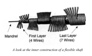
Put simply, a flexible shaft is a precisely defined and configured nested group of springs, tightly wound so that it has torsional or rotational strength, as opposed to the tensile strength found in standard wire rope or cable, to which flexible shafts bear a resemblance. What makes flexible shafts specifically useful is that flexible shafts can bend, but also still rotate. In other words, a flexible shaft transmits rotary motion much like a solid shaft, but it can be routed over, under, and around obstacles that would make using a solid shaft impractical.

A flexible shaft assembly consists of a rotating shaft (sometimes called a core) with metal end fittings for attachment to mating parts. A protective outer casing is used when necessary. This casing has its own fittings (called ferrules) that keep it stationary during use and can serve as an environmental protection.
A flexible shaft is a highly effective means of transmitting rotary motion and is more efficient than universal joints, gears, sprockets and chains, and belts and pulleys. It is typically lower in cost than these other devices and offers the added benefit of compensating for misalignments. Flexible shaft assemblies are successfully used in everything from 787 airplanes to children’s toys. Their exceptionally long lives are not affected by continuous operation at speeds up to 50,000 RPM, and they can withstand temperatures ranging from -300 degrees to 1000 degrees Fahrenheit.
Aerospace Applications
Flexible shafts are used in a great variety of aerospace applications, as their characteristics perfectly meet the challenges of aerospace manufacturing. Some common or especially vital applications include thrust reverser actuation systems (TRAS), flap actuation, valve override systems, pedal adjustment systems, rescue hoists, afterburner nozzle actuation, canopy actuation, refueling tubes, and more.
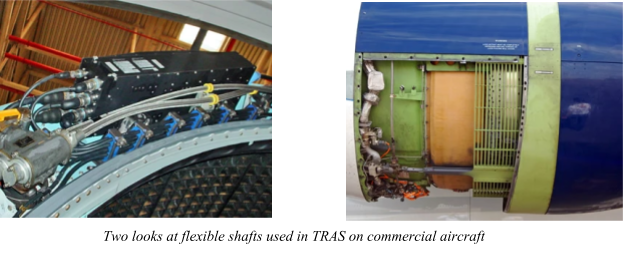
Flexible shafts are a key part of TRAS systems on many large commercial aircraft. TRAS systems are essentially an engine break for these aircraft. Located at the back of the engine, the thrust reverser of a turbo fan / jet engine essentially closes the by-pass and diverts the thrust forward to slow the plane. In forward motion, the thrust comes in the intake and out the exhaust and by-pass. In the stop motion, the thrust comes in the intake and since the by-pass is closed, the thrust reversers divert the by-pass flow through forward facing matrices, causing the plane to stop. There are four flexible shafts used in this system, which synchronize and connect the actuators that open both halves of the thrust reverser. There are two other flexible shafts used in the trans cowl lock, which keep the TRAS from deploying while in flight.

Another notable application in which flexible shafts are deployed is in the flap and slat systems, especially on slightly smaller aircraft, such as business jets. Flaps and slats are moveable wing surfaces that extend during takeoff and landing to change the wings’ profile to produce “high lift” at lower airspeeds. During flight, flaps and slats retract to reduce wing area and drag at higher speeds, increasing efficiency. The configuration of a flap and slat control system is very similar in most aircraft. Each surface is driven by linear actuators, which are connected to a transmission system centrally controlled from a power drive unit. Flexible shafts transmit the rotary motion from the motor out along the wing to drive the actuators that enable the flap and slats to extend and retract.
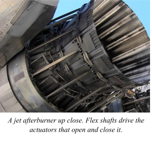
An especially demanding application in which flexible shafts are used is that of fighter jet afterburner nozzle control systems. A fighter jet afterburner is comprised of a set of fuel injectors, a tube, a flame holder that the fuel burns in, and an adjustable exhaust nozzle. The actuators controlling the nozzles opening and closing are driven and synchronized by a series of flexible shafts that ring the engine. These flexible shafts are highly engineered to withstand the extreme temperatures and torque loads presented by this demanding application.

Why Flexible Shafts?
While some applications in which flexible shafts are deployed appear extremely complex or demanding, other applications seem straightforward. However, flexible shafts are a constant in all these applications. In fact, flexible shafts are often the preferred choice in aerospace applications for rotary motion transmission over gear boxes, universal joints, and belts-and-pulleys.
Why is it that flexible shafts are the best technology to use in so many aerospace applications? There are a number of reasons, and while many of these reasons depend upon the specific application at hand, there are other, more general reasons for the flexible shafts’ superiority that hold true across almost all applications.
In general, flexible shafts are the preferred rotary motion transmission device because they:
-
Eliminate alignment problems: Flexible shafts have no need for the tight tolerance that solid shafts require.
-
Are more efficient: Flexible shafts are typically 90 to 95 percent efficient. Gears, U-joints, belts and pulleys have much lower efficiencies due to greater frictional losses.
-
Are both lightweight and powerful: Flexible Shafts have a 3:1 weight advantage over other design solutions while transmitting greater power loads.
-
Are less susceptible to vibration: Vibrations, a constant occurrence on aircraft, do not affect flexible shafts performance.
-
Reduce parts cost: Bearings and housings for solid shafts and gears require precise machining operations. Flexible shafts eliminate the need for such demanding tolerance and their excessive costs.
-
Are easy to install: Flexible shafts can be installed without the need for precise alignment or special installation tools.
-
Have a lower installation cost: Flexible shafts install in minutes without special tools or skills. Solid shafts, gears, pulleys, and universal joints require precise alignment and skilled mechanics for their installations.
-
Allow large off-sets: Flexible couplings allow only five degrees of off-set and U-joints 30 degrees, but with a 40 percent-50 percent decline in efficiency. Flexible shafts permit a full 180 degree off-set while maintaining their high efficiency.
-
Can be designed in the latter stages of a project: Unlike other rotary motion devices that need to be designed around because of their rigidness, defined configurations, and large mass, flexible shafts allow greater design freedom because engineers have only one piece to work on, eliminating complex coordination of multiple pieces.
-
Provide greater design freedom: Flexible shaft technology offer limitless possibilities in position motor and driven components.
The last point is especially important. One company, S.S. White Technologies, has been designing flexible shafts since 1874 (interestingly, the first one was used in dental equipment) and are now a leading manufacturer of them for aerospace applications. Many of S.S. White’s flexible shafts are designed custom for each application to maximize their efficiency and effectiveness. This is part of the beauty of the flexible shaft. Each individual flexible shaft assembly can be carefully designed and created to meet the needs of a specific application. If one application needs exactly this much torsional strength or power, the flexible shaft can be made to match that exactly. This is not easy to do. Flexible Shafts are a surprisingly complex product and is not easily modeled by simple calculations. For example, one of the most challenging aspects of designing a flexible shaft is balancing the opposing properties of bending flexibility and torsional deflection. For S.S. White technologies, this problem is solved with a program called Perflexion, a proprietary computer modeling software based on the pioneering work of Dr. Adam Black. It is a powerful tool that allows design engineers to optimize the performance characteristics of a Flexible Shaft. Prior to the use of Perflexion it was nearly impossible to optimize one of a flexible shaft’s characteristics. With Perflexion, S.S. White can now fully model the behavior of all the wires within a flexible shaft and arrive at a design that provides maximum bending flexibility while allowing minimal torsional deflection with 20 to 30 percent improvement above accepted industry standards.
S.S. White can serve as an example of the limitless possibilities held by flexible shafts in aerospace applications. When transmitting rotary motion , especially in a tight space, the flexible shaft cannot be beat in its efficiency, effectiveness, cost, versatility, and durability. An argument can be made for the flexible shaft being one of the backbones of the aerospace industry, and it isn’t difficult to see why. From windshield wipers to TRAS systems to jet afterburners, flexible shafts are there, doing their job quietly and efficiently, unbeknownst to many, but indispensable to all.

Steve Grimes began his career as an aerospace design engineer. Today he serves as director of sales and marketing for S.S. White Technologies, Inc., and is general manager of the company’s United Kingdom manufacturing plant.
The content & opinions in this article are the author’s and do not necessarily represent the views of ManufacturingTomorrow
Featured Product

